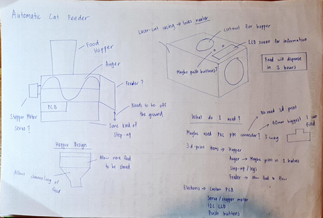
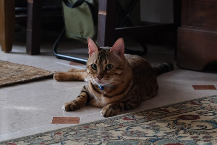
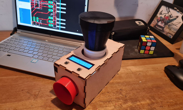
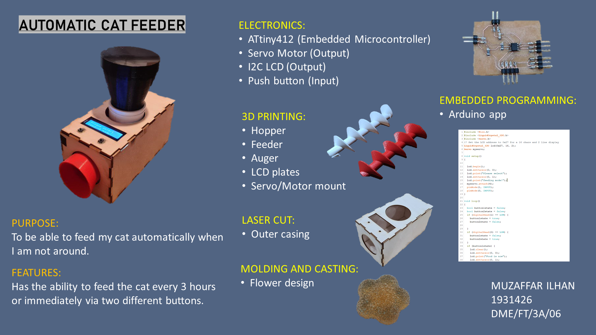
For the final module project, I have decide to make an automatic cat feeder. I have a cat named Cheetah and he eats a lot. That got me thinking into designing and making an automatic feeder for him. However, to make it a little more challenging, I will be implementing a lcd I2c screen to display messages and push buttons for different modes of feeding.
As for planning, I simply drew out some rough ideas on a page. It has been quite a while since I drew anything so it was nice to stretch my fingers.
Custom PCB board
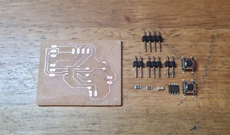
Electronics needed:
Custom PCB board
4,3 and 2 pin headers
0.1uf capacitor
2 x 1002 resistors
Attiny412
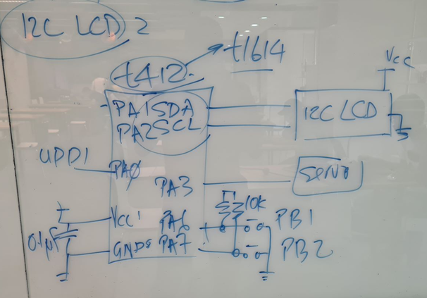
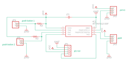
This being the first time designing, I asked Mr Steven to help me out. So we designed a rough idea of how the board would look like on the whiteboard. Since I did not need too many pins, I opted to use the attiny412 as my main processor. I will be implementing 2 push buttons and an I2c lcd.
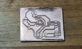
I started out by designing the cicuit via eagle. It took quite some time to route the lines for the board. I tried using the autoroute function but the results were not to my liking. So I manually routed the lines.
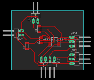
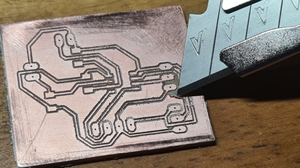
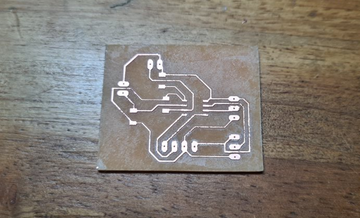
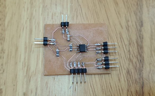
Next , I milled the board using the stepcraft machine. Here you can see the milled board. Fortunately for me, I only had to mill the board once. I am not very confident in my soldering, so I decided to slowly peel the unused copper. I did so with a pen knife and carefully peeling it afterwards. It took quite a bit and my fingers were starting to hurt. The finished product was very satisfiying as I could see the individual copper lines. Afterwards, I layed the components that were going to be soldered.
Here is the how the boards looks like after soldering. I was pretty impressed with how my soldering turned out. The board look much better from my previous attempts in soldering.
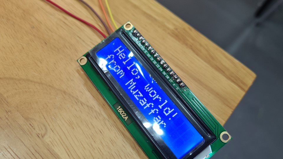
After soldering, I double checked the connections with a multimeter before trying out simple codes for the components that will be used. You can see below that I managed to successfully input a simple servo coding as well as a hello world for the I2c LCD. It did however take lots of trouble shooting for the I2c as it was outputting error codes. Fortunately after a bit of help from Mr Steven, it turns out that the SDA and SCL wires were mixed up.
 (Click here to download presentation file)
(Click here to go to Youtube Video on Module Project)
(Click here to download presentation file)
(Click here to go to Youtube Video on Module Project)