Embedded Programming:
Input devices
An input device is any equipment that is used to input data and signals to an information processsing system in this case, the Arduino board. An example would be a toggle switch. It inputs either a 0 or 1 into the circuit based on its position. A simple example would be an on-off button. Here are a few more examples:- Push button switch
- Ultrasonic sensor
- Motion detectors
- Light dependent resistors
- Mounting tape
Output devices
An output device is aany equipment that converts information like binary codes into human-readable form. An example would be the I2C lcd which display prints via the print function. Here are a few more examples:- LED displays
- Servo motors
- Stepper motors
- Relays
Assignment
For this assignment, I was tasked to read a microcontroller data sheet and program my board to do something. Since I had already milled and soldered my board for my final project, I decided to use it to demonstrate it here. I will be talking about the ATtiny412 since that is the board that I will be using in my project. The image below is from Microchip Technology.

Below you will be able to see the datasheet and pin configuration for the ATtiny412. The images and information below are credited to Spence Konde as well as Noora Nyberg and Adrian Torres from Fablab Academy.

 The Board consists of only 8 pins but still packs a punch. It has
- Max voltage of 6V, Min voltage of -0.5V
- A 16 MHz internal clack
- A 20MHz internal clock
- 256 B SRAM
- 128 B EEPROM
From the pin configuration above, you can see that pins available are:
- VCC: Power Supply
- GND: Ground
- Digital pins: PA0, PA1, PA2, PA3, PA4, PA5, PA6.
- Analog pins: PA1, PA2, PA3, PA4, PA5, PA6.
- UPDI Programming pin: PA0
- External Clock Pin: PA3
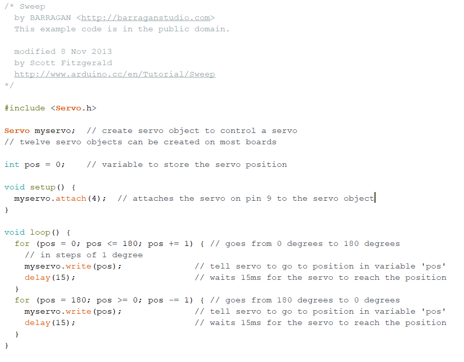
For my board programming, I wanted to test if my board's connection was good. So I connected the servo and updi programmer to my board before connecting to my computer. As for the code I used the example sweep servo code in the Arduino programmer. I used a code for arduino uno but just changed the pin number in the coding from 9 to 4 since I designed my servo to use the analog 4 pin on the ATtiny412.
Circuit in Thinkercad: